Did this site save
(or help earn) you money?
Say thanks with a
small donation.
|
The
TWI Designjet Documents library presented here as a courtesy of
ComputerCareOnline.com
The owners of this website have no affiliation to Hewlett Packard nor do we
claim to represent HP
in any way shape or form.
Return
to TWI Documents Library Index Page
|
HP
Designjet 600 Series Printers - System Error 030001-030003, Switch Power Off Check Pen Path, Noise Along Carriage Path

In this document:

KRS document number: BPP90033
Last updated: 09-Oct-2001
Minimum skill level: 2
The errors listed in the document title are displayed when the
pen carriage cannot move. Common causes are obstructions in the carriage path, excess friction along the carriage path, the
cutter failing to reach its home position, and worn or damaged Y-axis
parts. Follow the steps listed in this document to accurately determine the cause of the failure and to replace the appropriate parts.
Parts required (part numbers are subject to change)
Check for obstructions in the carriage path
- Manually move the carriage to the home position on the right and left sides, check for resistance along the carriage path.
- Check for any obstructions causing the
cutter not to reach its home position.
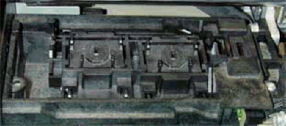
- Check that the Service Station sled housing is installed correctly (see Figure 1).
Figure 1: Correctly installed Service Station Sled

- Check carriage and
encoder interaction. The carriage and the
encoder should not touch anywhere along the Y-axis.
- Check both main and
small belts for missing teeth or fraying.
Wipe the entire rail with a soft cloth. Place four to six small drops of lubricant on a soft cloth to
lubricate the
rail.
Wipe the
encoder strip with a water-dampened soft cloth. Check for visible damage. If necessary, replace the
encoder
strip.
Perform a Y-friction service test
- Turn the printer on.
- Press ENTER.
- Use the arrow buttons to scroll to the Utilities menu display.
- Press ENTER.
- Simultaneously press the ENTER and UP arrows to access the Service Tests submenu.
- Use the arrows to scroll to Y-FRICTION.
- Press the ENTER button to begin the test.
The pen carriage will move along the slider rods with and without the
cutter
assembly. A range of PWM signals is required to move the carriage and is measured and displayed for both cases (with and without the
cutter). The test is used to check for excessive friction in the Y-axis. Excessive friction could cause server shutdowns.
The display will show four numbers: the first number is with the
cutter engaged, and the last three numbers are with the
cutter disengaged. Replace Y-axis parts if the values are greater than 90. If Y-axis parts are replaced, perform the calibrations as listed below.
Edge sense calibration
- Press ENTER at the Status display.
- Use the arrow buttons to scroll to the Utilities main menu. Press ENTER.
- Simultaneously press the ENTER and UP arrow buttons to access the Service Test menu.
- Scroll to EDGE SENSE CALIB, and press ENTER.
- Messages on the display will indicate when to load media for the calibration to proceed. Part of the calibration procedure is an automatic performance of the pen alignment procedure. The calibration takes approximately four minutes to complete.
- Stay in the Service Tests submenu to perform the next calibration.
Drop detect calibration
- Using the arrow buttons, scroll to DROP DETECT CALIB, and press ENTER.
- Press ENTER when calibration is complete.
- Stay in the Service Tests submenu to perform the next calibration.
Accuracy calibration
- Use a sheet approximately 24 x 36 inches or roll media. To get the best results for an accuracy calibration, use a polyester/matte film.
NOTE: If a polyester or matte/film is not available, use HP coated media when performing an accuracy calibration.
- Load the media. If using D-size media (24 x 36 inches) load the short edge as the leading edge in 24-inch models and the long edge as the leading edge for 36-inch models. E-size media (36 x48 inches) can also be used on 36-inch models.
- Using the arrow buttons, scroll to ACCURACY CALIB, and press ENTER.
- Press the UP arrow to select CREATE PLOT. A "Creating calibration plot" message will appear.
- Wait until the "Remove Media/Continue" message displays, then remove the media.
- Press the DOWN arrow button to scroll to CONTINUE. The "Create plot / Measure plot" message displays.
- Press the DOWN arrow button to select MEASURE PLOT.
- Rotate the plot so the edge with arrows point to the leading edge, reload the plot with print side down.
- The printer will load the plot and measure the alignment marks using the edge sensor on the pen carriage.
- Press the DOWN arrow button to continue when the "Calibrate done/Continue" message displays and the plot feeds out. The accuracy calibration is now complete.
- Verify printer functionality. Perform media loading procedures with roll and sheet (preferably larger than 8.5 x 11 inches) media, two times each.
Copyright Hewlett-Packard Co. 2001
This information is subject to change without notice and
is provided "as is" with no warranty.
Hewlett-Packard shall not be liable for any direct,
indirect, special, incidental or consequential damages
in connection with the use of this material.


![]()
![]()
