Did this site save
(or help earn) you money?
Say thanks with a
small donation.
|
The
TWI Designjet Documents library presented here as a courtesy of
ComputerCareOnline.com
The owners of this website have no affiliation to Hewlett Packard nor do we
claim to represent HP
in any way shape or form.
Return
to TWI Documents Library Index Page
|

In this document:

KRS document number: BPP90047
Last updated: 28-Feb-2002
Minimum skill level: 3
End of Support Drawer Statement
Hewlett-Packard guarantees support for five years after the end of production of its large format printers. Since the HP Designjet 650C has been out of production for a number of years, the parts and sub-assemblies may no longer be available to complete the repair. If the customer has a service agreement or contract, follow normal contract call logging processes (regardless of parts availability).
If the printer is not covered by a service agreement or contract, notify the customer about parts availability issues that will limit the ability to perform printer repairs. Inform the customer about the benefits of HP's Trade Up program, and give them the Trade Up Web site http://www.hp.tradeups.com/login/login.asp. If the customer needs help in locating a local reseller, give them the reseller contact Web site at http://www.hp.com/usa/reseller/index.html. If the customer still requests service and parts are available, follow normal trade call logging processes to avoid escalation. If parts are unavailable for the needed service, do not log a CSO.
Introduction
Bail issues can generally be determined if printer causes media crash during loading or gives System Errors 010011, 010012, or 010013. The most common parts related to these failures are the Bail Lift Mechanism and the Bail. The Bail Sensor and the Bail Sensor Flag can also cause the same symptoms. Follow the steps listed below to accurately troubleshoot the issue, and replace the appropriate parts.
Parts required (part numbers are subject to change)
NOTE: If any of the troubleshooting steps listed below solve the problem, attempt to verify printer functionality by printing several internal prints. If functionality is verified, no additional parts should be replaced.
Troubleshooting steps
- Turn the printer off and remove media if loaded.
- Turn the printer on and open the window when the Out of Media message appears.
- Insert a pencil or other object into window sensor opening to keep sensor switch depressed.
- Attempt to load media. Watch for the Bail to lift as advancing media approaches (approximately 1 inch) and should go back down so the Starwheels are resting on media surface.
- If advancing media goes over top of Bail due to little or no Bail lift, continue with the Bail Calibration and Troubleshooting section.
- If gives System errors 010011 or 010012 during media loading attempt, continue with the Bail Sensor test and Troubleshooting section listed below.
Bail sensor test and troubleshooting
- Power down printer, then power up again.
- At the Out of Media prompt, press ENTER.
- Use the arrow buttons to scroll to the Utilities menu, then press ENTER.
- Simultaneously press the ENTER and UP arrow buttons to access the Service test menu.
- Using the ARROW keys, scroll to Bail sensor test and press ENTER.
- Display should read BAIL DOWN at this time.
- Manually lift Bail. Display should now read BAIL UP.
- If display does not reflect position of Bail (BAIL UP or BAIL DOWN), check for obstructions preventing Bail movement.
NOTE: Possible obstructions can include the pen Carriage,
cutter not positioned at the far right, or the Bail itself may be bent.
- When free movement of Bail is assured, manually raise Bail again. Display should read BAIL UP.
- If display does not read BAIL UP when the Bail is lifted, locate Bail sensor flag on service station.
- Manually depress and release the Bail sensor flag.
- If the display does not reflect proper position of Bail, visually check that the flag is properly attached and moves freely. Clean the flag with a cotton swab dampened with water to assure proper movement. Replace the Bail sensor flag if needed.
- Once proper flag movement is assured, check for proper display message as outlined in step 11.
- If the display still doesn't reflect proper position of Bail, replace the Bail sensor.
- Perform the Bail sensor test to verify proper operation.
- Perform Bail calibration as outlined in Steps 1-9 of Bail Calibration and Troubleshooting section.
- Exit calibration by pressing PREVIOUS button until at Out of Media prompt on display.
- Verify functionality by loading media and printing several internal prints.
Bail calibration and troubleshooting
- Remove media if loaded.
- At the Out of Media prompt, press ENTER.
- Use the ARROW keys to scroll to the Utilities menu and press ENTER.
- Simultaneously press the ENTER and UP arrow keys to access the Service test menu.
- Use the ARROW keys to scroll to Bail calibrate and press ENTER.
- Display should read step Bail (00)
- Press the UP arrow key. Bail should rise slightly and numbers in parenthesis on display should increment by two with every press of UP arrow button.
- Continue pressing UP arrow key until Bail drops slightly and press ENTER.
- Display should read SUCCESS CALIBRATION; press ENTER.
- If calibration fails or Bail lifts very little, check for obstructions preventing Bail from lifting.
NOTE: Possible obstructions include the Carriage being in the way, or the
cutter is not positioned at the far right, away from the Bail.
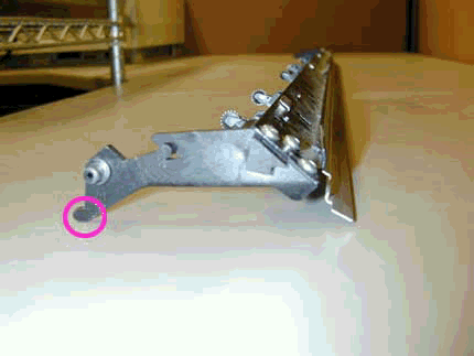
- If no obstructions to Bail movement are found, remove the Bail and check the left side pivot arm for damage or excessive wear. See Figure 1 for illustration.
Figure 1: Pivot arm where damage usually occurs

- If pivot arm is damaged or excessively worn replace the Bail, and install the Bail lift mechanism kit. Following replacement perform a Bail calibration.
- If no problems are found with Bail or pivot arm, install Bail lift Mechanism kit as instructed below.
Install the Bail Mech Upgrade Kit
- Remove the window assembly and the left end cover.
- Remove the bail assembly, the
encoder
strip, and the service station.
- Remove the media-axis motor.
- Remove the
cutter assembly and the carriage.
- Remove the overdrive clutch and the overdrive assembly.
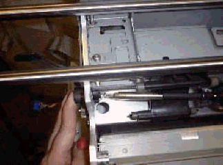
NOTE: Lift the right side of the Overdrive up about two inches and pull hard to the right. DO NOT break or lose the white nylon bearing.
Figure 3: White nylon bearing

- Remove the old Y-tensioner bracket.
- Use scissors or needle-nose pliers to remove teflon or spring washers if present.
- Install new Engaging lever/gear into sideplate. Attach Auto Cam onto Engaging gear shaft.
- Use two screwdrivers to securely fasten the Auto Cam onto the Engaging gear to ensure a tight fit.
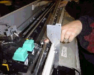
- Insert the tightening screw into the Auto Cam. Place a finger on the Cam gear as you tighten the screw into position.
NOTE: The screw must go in straight and be flush; the plastic screw will create the threading and must not be over-tightened. Otherwise, a new Bail-Mechanism kit must be ordered.
Figure 5: Cam gear being tightened

- Attach new Y-Tensioner bracket onto the sideplate with support gear cam in the slider position.
- While firmly pressing the Support Gear Cam into the Cam Gear, insert the two plastic screws.
- Test the new bail mechanism by pressing down on the engaging lever. All of the cams should spin freely.
NOTE: If you feel any lateral movement in the Engaging lever, loosen and refasten the Support Gear Cam into the Cam Gear.
- Attach spring to the Engaging lever and Y-Tensioner bracket assembly.
- Reassemble the printer.
- Perform a Bail calibration (listed above).
- Perform an Edge sensor calibration (listed below).
- Ensure printer functionality.
Edge Sense Calibration
- Press ENTER at the Status display.
- Use the arrow buttons to scroll to the Utilities main menu. Press ENTER.
- Simultaneously press the ENTER and up arrow buttons to access the Service Test menu.
- Scroll to Edge Sense Calib and press ENTER.
- Messages on the display will inform you when to load media for the calibration to proceed. Part of the calibration procedure is an automatic performance of the pen alignment procedure. The calibration takes approximately four minutes to complete.
Copyright Hewlett-Packard Co. 2001
This information is subject to change without notice and
is provided "as is" with no warranty.
Hewlett-Packard shall not be liable for any direct,
indirect, special, incidental or consequential damages
in connection with the use of this material.


![]()
![]()


