Did this site save
(or help earn) you money?
Say thanks with a
small donation.
|
The
TWI Designjet Documents library presented here as a courtesy of
ComputerCareOnline.com
The owners of this website have no affiliation to Hewlett Packard nor do we
claim to represent HP
in any way shape or form.
Return
to TWI Documents Library Index Page
|

In this document:

KRS document number: BPP90187
Last Updated: 24-Jun-2002
Minimum skill level: 1
Introduction
Follow the directions below to setup an HP Designjet 500 or 800 series printer.
Assemble the stand
- Separate the stand from the paper bin. Set aside the cardboard tray inside which separates the components of the paper bin from those of the printer's stand. This provides access to the stand components.
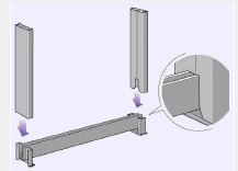
- Attach the legs to the outside of the cross brace.
Figure 1: Attach the legs to the cross brace

- Insert eight screws into the legs. Use the smaller screws with washers.
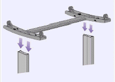
- Position the horizontal foot brace onto the feet. Push the foot brace into the slot in each foot.
- Position the feet on the legs assembly.
Figure 2: Position the feet onto the legs assembly

- Secure the feet to the legs with ten screws and the torx driver wrench supplied with the printer. Again, use the smaller screws with washers.
Attach the stand to the printer
- Check that all the stand screws are tight. If you can't tighten all the screws properly, try unscrewing one or two so that the legs, feet and cross braces are properly aligned, and then retighten them.
- Ensure all four brakes are applied.
- Turn the stand the correct way up.
- Put the printer onto the stand assembly.
- Secure the stand with four large flat-head screws (the two screws on the right-side can be tightened until secure).
CAUTION: Do not tighten the screws on the left side of the printer too tight. They are manufactured to remain somewhat loose and allow the printer to be self-leveling. This is to compensate if the printer is installed on an uneven surface, because torque may be applied to the printer and can damage it.
Assemble the paper bin
- Insert the four bars into the slots in the right bin holder, and then mount the left bin holder onto the four bars.
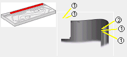
- Remove the bin "film" from its container. You will need to form five creases in the film so that it will fit properly into the bin holders. Four of these creases are 1 cm (3.9 inches) and 2 cm (7.87 inches) from each end, both in the same sense, with an orientation circle on the outside. The third crease is also in the same sense, and 9 cm (35.4331 inches) from the end farthest from the orientation circle.
Figure 3: Bin film creases

1- 1 cm (3.9 inches)
2- 7 cm (27.55 inches)
- Slide the bin film into the groove in the bin holders, and bend it into position. Insert the end with the two creases first. Slide the film fully to the end so that the creases are in the correct positions.
- Clip the film into place at one end.
- Attach the two caps to this end of the film.
- Clip the film into place at the other end.
- Attach the two caps to this end.
- Clip the end pieces to the film and sides.
- The bin is now assembled.
- Peel off the orientation circle.
- Attach the right adapter to the printer stand. It is marked with the letter `R' and must be attached to the front part of the right leg. First hook the bottom into its slot and then raise it into place; two clicks should be heard as the top is clipped in.
- Attach the left adapter to the printer stand. It is marked with the letter `L', and must be attached to the front part of the left leg.
NOTE: If the adaptor needs to be removed, unclip the two latches near the top and insert a pencil or similar tool into the hole to release each latch.
- Insert the bin onto the adapters. Hold the bin horizontally and insert the small pins into their slots.
- Raise the bin into its correct position (raise the bin until the large pins align with their slots and the bin drops into place).
Turning on the printer
After attaching the power cord to the power socket in the back of the printer, turn the printer on with the on/off push button (a soft button located on the left side of the front of the printer).
The printer's front panel menu and all the printer's internal files are available in the following languages: English, German, Spanish, French, Italian, Japanese, Portuguese, Korean, Traditional Chinese Simplified Chinese, and Catalan.
The printer will prompt for language selection upon the initial startup of the printer.
Priming the ink system
The 500 and 800 series printers use the HP modular ink system delivery system. The ink supply includes both printheads and ink cartridges.
When the printer is first turned on it will ask for ink cartridges.
NOTE: Four setup printheads are already installed in the carriage. Leave these printheads in the printer until the setup procedure is complete and the printer prompts to replace the setup printheads with the normal printheads.
The printer will automatically run the priming procedure.
Altitude setting
The 500 and 800 series printers contain a vacuum pump, which is used to hold the media onto the platen. The altitude of the printer location affects the efficiency of this pump. Specify the altitude to ensure the pump operates correctly.
To set the altitude follow the steps below:
- On the printer's front panel, scroll to the Set-up menu (printer icon in lower right-side of the display) and press ENTER.
- Scroll to Altitude and press ENTER.
- Scroll to the required value (0 - 1000 m, 1000 m to 2000 m, or > 2000 m) and press ENTER.
- Press the BACK key to return to the main menu.
- The printer setup is now complete.
The following table shows the corresponding altitude values in feet.
Meters
| Feet |
0 -1000 |
0 - 3300 |
1000 - 2000 |
3300 - 6600 |
>2000 |
>6600 |
Copyright Hewlett-Packard Co. 2002
This information is subject to change without notice and
is provided "as is" with no warranty.
Hewlett-Packard shall not be liable for any direct,
indirect, special, incidental or consequential damages
in connection with the use of this material.

Back
to TWI Documents Library Index Page


![]()
![]()


